IT Infrastructure Diagram (Revised)
IT Infrastructure Diagram Explanation (Revised)
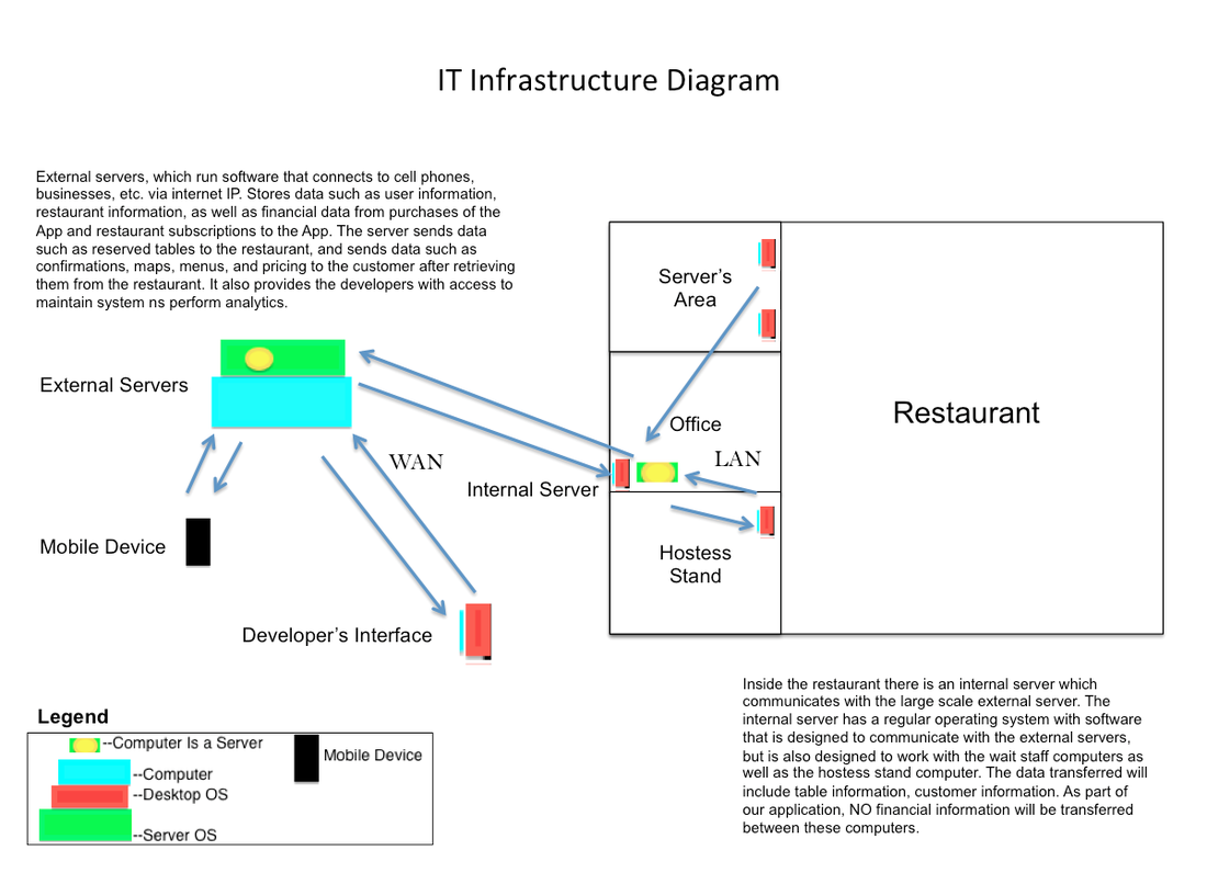
The IT infrastructure will consist of three layers: WAN Server System, LAN Server System, and Local Computer System. The WAN (Wide Area Network) will consist of a network of servers across a region that will communicate with each other as well as cell phone service providers to communicate with the mobile devices that will run the app that we are providing. These servers will also communicate with an in house computer in the restaurant, the start of the internal star topology that will be located in a manager’s office. The in house computer will retrieve data from the external servers, such as requests for tables. The in house computer will transmit menus, pricing, tables and times available. The computer will also serve as a restaurant control panel for the manager, wherein he can view the number of guests, occupied tables, records for the day, customer flow data, and the guests that were entered via APPetite and ones that walked in. The internal computer will also communicate with wait staff computers to get
data about which tables are in use, as well as communicating with the hostess computer to get data about customers that walk in, while giving information to the hostess computer about the guests that will be arriving with an APPetite reservation. The users devices will communicate with the large external system ONLY, and not with the internal system so that the larger system will handle the requests, which will make data transfer faster and cheaper as the data will be stored primarily in one area to be distributed, as opposed to in multiple places and distributed on a request by request basis to the restaurant. The external server will also be accessible to Appetite developers through a back-end link so that they can perform system administration and collect usage and marketing data from the system.
data about which tables are in use, as well as communicating with the hostess computer to get data about customers that walk in, while giving information to the hostess computer about the guests that will be arriving with an APPetite reservation. The users devices will communicate with the large external system ONLY, and not with the internal system so that the larger system will handle the requests, which will make data transfer faster and cheaper as the data will be stored primarily in one area to be distributed, as opposed to in multiple places and distributed on a request by request basis to the restaurant. The external server will also be accessible to Appetite developers through a back-end link so that they can perform system administration and collect usage and marketing data from the system.
Revision Explanation
The IT infrastructure diagram was revised to show a more abstract representation of the IT systems involved in the functioning of the App. We felt that overlaying the IT systems on the physical model restricted the diagram and made it less clear to potential clients. Some IT elements were added based on research done for our plan moving forward and budget projections, specifically, the addition of an administrative back-end. Revisions are italicized.
IT Infrastructure Diagram (Previous)
The IT Infrastcructure diagram maps out the physical relationship between all of the aspects of the Consolidated Physical Diagram, along with the abstract physical relationship of the other IT aspects of the application.
IT Infrastructure Diagram Explanation (Previous)
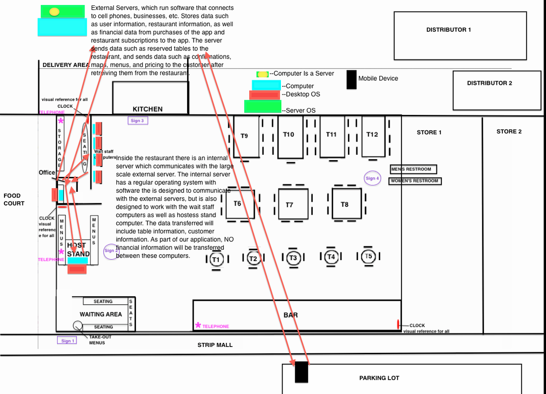
The IT infrastructure will consist of three layers: WAN Server System, LAN Server System, and Local Computer System. The WAN (Wide Area Network) will consist of a network of servers across a region that will communicate with each other as well as cell phone service providers to communicate with the mobile devices that will
run the app that we are providing. These servers will also communicate with an in house computer in the restaurant, the start of the internal star topology that will be located in a managers office. The in house computer will retrieve data from the external servers, such as requests for tables. The in house computer will transmit menus, pricing, tables and times available. The computer will also serve as a restaurant control panel for the manager, wherein he can view the number of guests, occupied tables, records for the day, customer flow data, and the guests that were entered via APPetite and ones that walked in. The internal computer will also communicate with wait staff computers to get data about which tables are in use, as well as communicating with the hostess computer to get data about customers that walk in, while giving information to the hostess computer about the guests that will be arriving with an APPetite reservation. The users devices will communicate with the large external system ONLY, and not with the internal system so that the larger system will handle the requests, which will make data transfer faster and cheaper as the data will be stored primarily in one area to be distributed, as opposed to in multiple places and distributed on a request by request basis to the restaurant.
